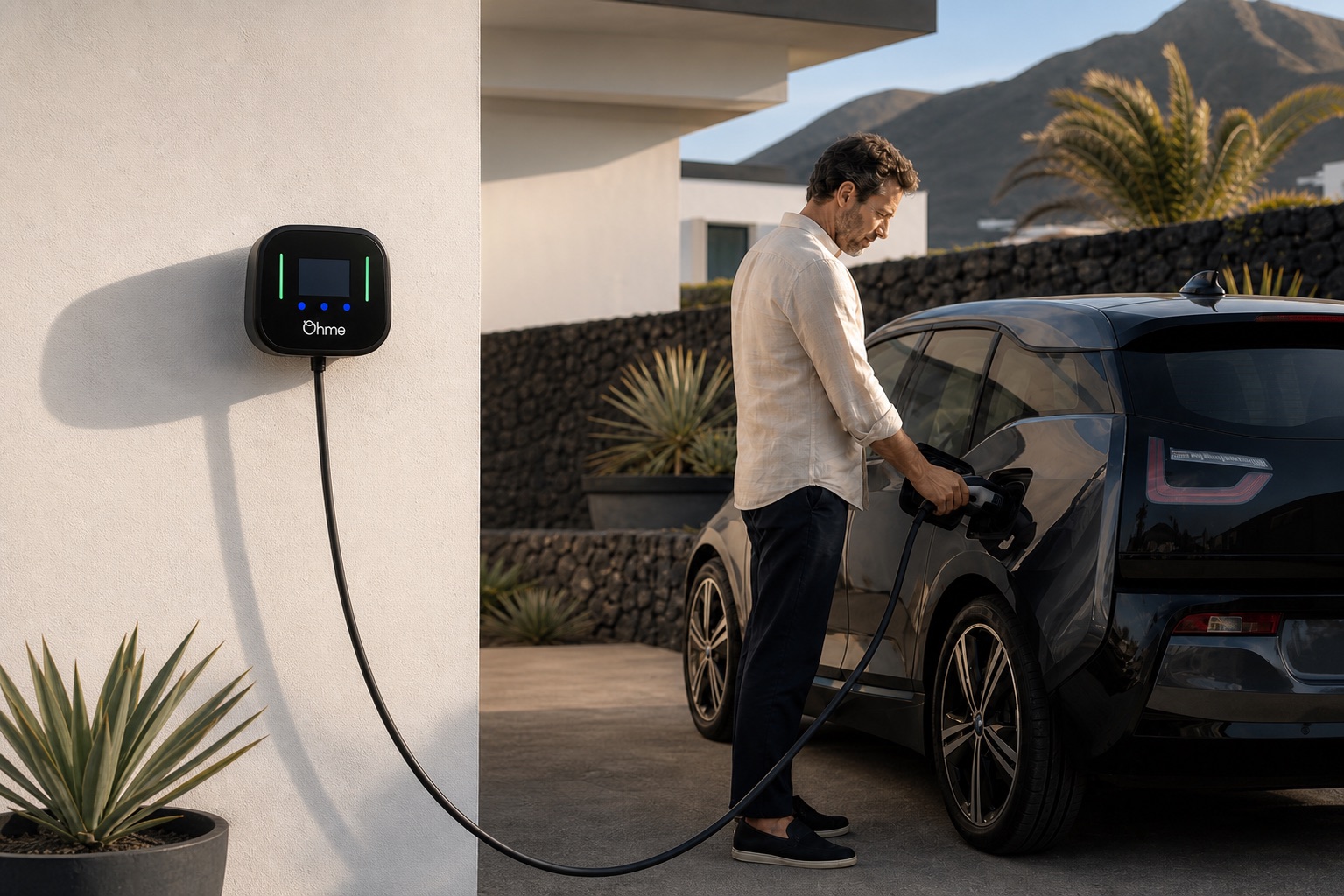
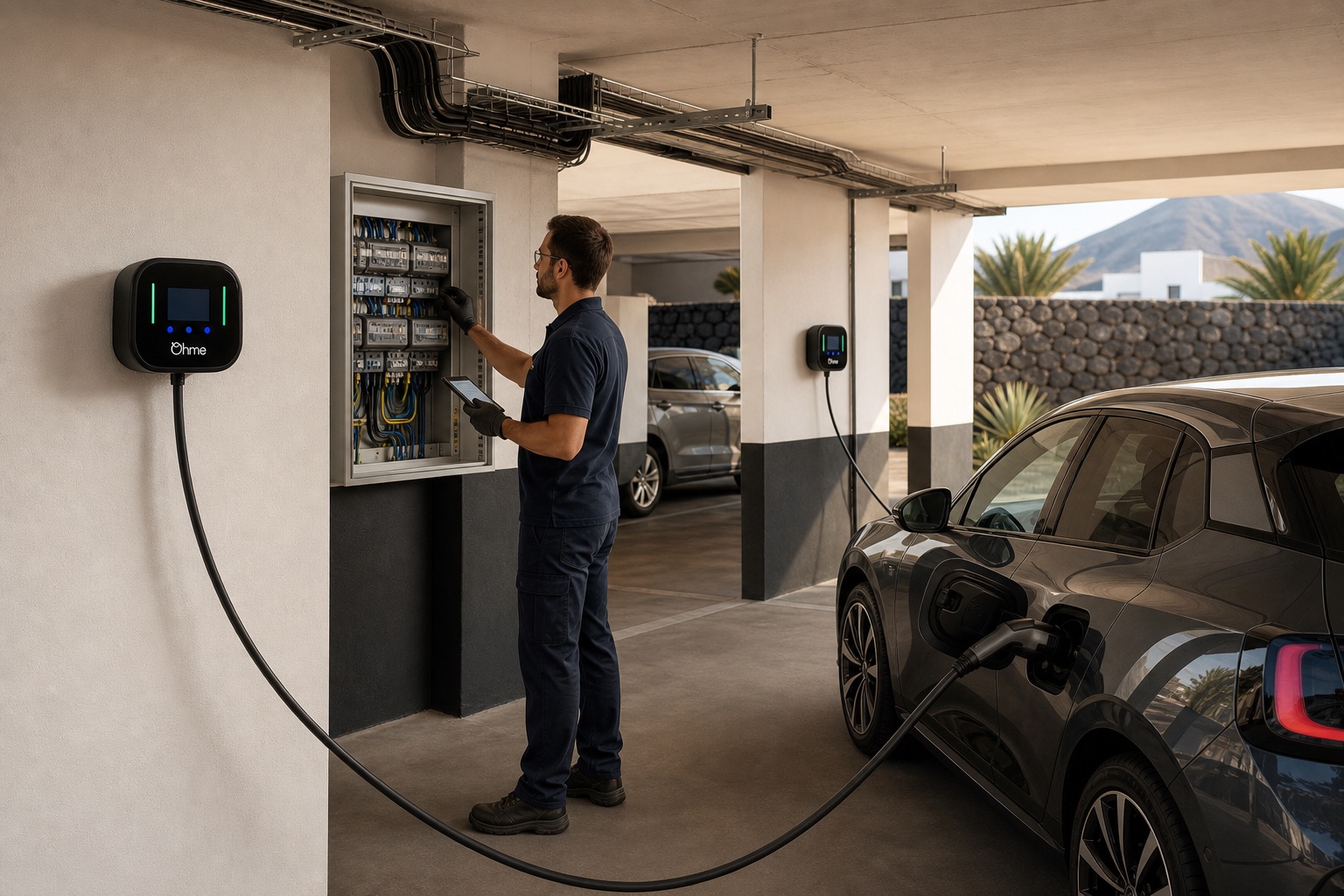
When installing an electric car charger, choosing the equipment and its power rating is not enough. The source of its power supply, how energy use will be measured and which parts of the installation will be individual or shared must also be defined. That decision is set out in the installation layout.
The ITC-BT-52 sets out four families and eight variants: 1a, 1b, 1c, 2, 3a, 3b, 4a and 4b. Choosing correctly allows consumption to be allocated, circuits to be sized, expansion to be planned and an installation to be designed coherently for the home, apartment building or business.
Installation layout and charging mode are different things
The layouts in ITC-BT-52 describe the relationship between the grid, meters, protection devices and charging stations. Charging modes 1, 2, 3 and 4, meanwhile, refer to how the vehicle connects and communicates with the charging point.
Saying that a charger operates in mode 3 therefore does not indicate whether it uses arrangement 2, 3a or 4a. These are different decisions: one defines the electrical architecture and the other the charging method.
Summary of the eight layouts covered
| Arrangement | How it is supplied | Metering and normal use |
|---|---|---|
| 1a | Shared backbone circuit from the existing centralised meter installation. | One main meter and secondary meters at the charging points. Apartment buildings with available space. |
| 1b | As for 1a, but from a new central meter bank for EV charging. | A shared solution when the necessary equipment does not fit in the existing meter bank. |
| 1c | Individual circuits from a shared charging installation. | A shared main meter and individual secondary meters in a centralised meter bank. |
| 2 | Individual circuit connected to the same meter as the home. | One electricity contract for home and car; optional secondary meter. |
| 3a | Individual circuit with a dedicated main meter. | Separate supply contract for the charger, using the existing centralised meter installation. |
| 3b | Like 3a, but with a new central meter bank. | It is used when the existing meter bank does not have sufficient space. |
| 4a | Individual additional circuit from the supply installation. | The usual option for single-family homes and rural properties with one electricity supply. |
| 4b | Additional circuit or circuits from the garage's communal supply. | Apartment buildings, businesses or car parks with a solution integrated into the communal services. |
Arrangements 1a and 1b: shared installation with a trunk circuit
In arrangements 1a and 1b there is a shared main meter for the charging infrastructure. One or more shared circuits run from it through the garage. Junction boxes supply each station and secondary meters record individual consumption.
Arrangement 1a: using the existing meter bank
The main charging meter is incorporated into the existing centralised meter installation. This is the first alternative recommended by the technical guide when spare modules are available or the centralised installation can be properly extended.
Its strength is that it creates tidy, shared infrastructure without needing another cabinet or room. In return, the owners' association must coordinate the shared installation, consumption allocation and future expansion.
Arrangement 1b: a new meter bank for the chargers
It works on the same trunk circuit principle as 1a, but the main meter and metering components are housed in a new central meter bank dedicated to charging. This is considered when the existing one cannot be extended or lacks the necessary technical space.
The application guide sets out an order of preference: first use spare meter modules, then extend the existing central meter bank, and use 1b where insufficient space makes a new central meter bank necessary.
Layout 1c: shared meter and individual circuits
1c also has a main meter for the charging system as a whole, but the secondary meters are grouped together and supply individual circuits to each station.
The difference from 1a and 1b lies in the distribution: it does not use the same trunk structure with branches along the garage. This can make each circuit easier to identify, although routes, space and voltage drop must be assessed before deciding.
Arrangement 2: one meter for the home and charger
Layout 2 uses the same main meter for the home and its charging station. At the outlet of the central meter bank, the home's individual supply cable and the individual circuit to the parking space branch off separately. A secondary meter may be added, but it does not replace the supply's main meter.
It allows a single supply contract to be retained, with power control handled by the main meter. The design or technical report must justify circuit protection and provide for how the supply will be operated or reset where appropriate.
Layouts 3a and 3b: one main meter for each charger
In arrangement family 3, each charging station has its own main meter. This creates a supply independent of the home or the rest of the building, with its own contract and metering.
Layout 3a: dedicated meter in the existing central meter bank
Available modules or an extension of the existing meter bank are used. An individual circuit runs from each meter to its charger.
Arrangement 3b: a dedicated meter in a new meter bank
Where there is no space for 3a, the chargers' main meters are placed in a new central meter bank. The guide applies the same order of priority as for family 1: first use or expand the existing installation and, as a last resort where there is insufficient space, create an additional central meter bank.
Layout 4a: individual additional circuit
Layout 4a incorporates a dedicated charging circuit from the supply's control and protection board. It is the typical solution for single-family homes and rural properties with one electricity supply.
In new single-family homes, ITC-BT-52 identifies this circuit as C13. It can also be used in certain jointly owned buildings where the communal infrastructure allows it, but the guide advises against widespread use in shared garages because numerous long cable routes can increase voltage drops and require large cable containment systems.
Layout 4b: from the garage's communal supply
In layout 4b, chargers are integrated as an extension of the installation supplying the garage's communal services. One or more additional circuits run from its distribution board and can be arranged individually or collectively.
It may be useful for a solution promoted by an owners’ association, car park, company or fleet. Energy supplied to vehicles must be metered and managed separately from other garage consumption.
How to choose the right arrangement
No layout is universally better than the others. The choice depends on the property and must be specified in the technical design report or project documentation, as applicable. Before deciding, it is worth checking:
- whether it is a single-family home, apartment building, business, car park or fleet;
- the space available in the central meter bank;
- ownership of the supply and who will pay for the energy;
- the distance and route to each parking space;
- the current and future number of chargers;
- the available power capacity and need for load management;
- protection devices, conductor cross-sections and voltage drops;
- maintenance and how costs will be shared.
Different layouts can coexist in the same building if they all comply with ITC-BT-52. Even so, when the first electric vehicle arrives in a shared garage, agreeing a common strategy can avoid untidy cable routes and make further installations easier.
What should be documented
Before carrying out the work, the installer or designer must prepare the relevant technical documentation and identify the chosen arrangement. The supply origin, metering, circuits, protection, load management system where present, and final checks must also be defined.
The Technical application guide for ITC-BT-52, revision 2 of September 2024, sets out the criteria and diagrams for the eight layouts. Its drawings are indicative examples and do not replace the complete design of each installation.
Frequently asked questions
Which layout is normally used in a single-family home?
Arrangement 4a is the usual reference: an additional circuit dedicated to charging, called C13 in new homes. It must be sized and protected for the actual charger and cable route.
What is the difference between arrangements 1a and 1b?
Both are shared layouts with a common backbone. Layout 1a uses or extends the existing centralised meter installation; 1b incorporates a new centralised meter installation for the charging infrastructure when there is insufficient space.
Can an apartment building combine different layouts?
Yes. ITC-BT-52 allows different layouts within the same building, provided each installation meets all applicable requirements and the shared infrastructure remains coordinated.